Inventing the wheel
There are a variety of devices that can sense light. Low-cost devices include LDRs (Light Dependent Resistor) and Photo Diodes. Of these two, LDRs are in general rather slow in their response (a few milliseconds up to 50 ms), and hence do not seem to be appropriate for a Beam Breaker device for a race timing system. Photo Diodes can respond very quickly to changes in light – some can switch in the picoseconds range. This is one of the reasons that, in optical communication systems, photo diodes are usually used.
The output signal of a photo diode is electrically a very small signal, and needs amplification before it can be used in a microcontroller or other standard electronic device. Besides simple amplification, noise reduction or cancellation needs to be performed using one or more of the techniques described in part 2. The design of such a signal processing circuit can be quite a project by itself. Luckily, designers of many remotely controllable systems (such as television sets), had the same design challenges, so that wheel is already invented. Various component manufacturers have integrated solutions with optical filters, signal de-modulation, (automatic) gain control, etc. and provide an "on/off" signal to be used directly by another device. Most of these detectors are compact, 3 pin, plastic devices, available for around 1 – 2 euro.
By moving into the design direction of these well designed Remote Control sensor devices, we also move in the direction of near infrared light. These wavelengths are not visible to the human eye but can be damaging to the eye, so non-diverging beams (e.g. infrared laser) are potentially very dangerous. For safety, we will, for now, only consider diverging beams. And by moving into the design direction of diverging beams, the distance is an important factor, as well as emitted power at “the source end” and sensitivity at “the sensor end” of the beam breaker.
Checking suppliers
Checking the websites of a few electronic component suppliers (https://www.mouser.com, https://www.farnell.com , https://www.digikey.com etc.) we can find many devices tuned for various brands of electronic devices (televisions etc.) and their remote controls. It appears that many manufacturers made their own infrared control system, not only in the coding of commands, but also varying parameters such as:
- Pulse frequency
- Burst length and gap length
- Infrared light wavelength
Detector device manufacturers cater the needs of all these brands by offering a wide range of products. Reading various data sheets learns that the receivers often include AGC (Automatic Gain Control), which helps eliminating noise signals from, e.g., fluorescent tubes (TL) and heavily dimmed LED lights. All the devices with AGC do seem to require gaps in the incoming signals (probably to train the AGC).
What we need is a fast-responding beam breaker. A preliminary design goal is an accuracy of less than 1 ms. The faster of the remote-control receiver components would nearly (maybe even completely) meet that goal, but the signal required is more complex (bursts and gaps) and detection would require more complex logic in the microcontroller. During a gap in the signal, there cannot be any detection done. This makes these kind of devices slower and less accurate. A rule of thumb seems that the stronger the AGC system, the slower the receiver will be for our needs (because of the longer gap required).
Note: The additional complexity in signal generation and detection should not be a show stopper, but the fact that a device with AGC can be slower or less accurate, may be.
Luckily, very similar devices are available with beam breaker (or light barrier) systems specifically mentioned as design goal. The main difference seems to be that these sensors do not have AGC and do not require gaps in the input signal. The main advantage is a fast response time (a few pulses delay, that could be less than 0.2 ms). The disadvantage is the lack of AGC, so sunlight and other infrared sources may be an issue, and the range is a bit limited compared to their AGC-equipped family members.
As some manufacturers provide both types which are pin compatible, we will first look into devices not requiring a gap in the signal (likely non-AGC).
Selecting a detector device
Our main goals for the beam breaker are sufficient detection speed and long range. So, we’ll look for a device with a short response time and high sensitivity.
As with most electronic components, manufacturers publish datasheets for their receivers. Often one datasheet is given for an entire family of devices, where each member is identical to the others but a few details. For Infrared sensors, the main distinctive feature is the optimum pulse frequency. In the datasheet, the response time is given in “number of pulses”, not actual time. This leads to the conclusion that a higher pulse frequency is preferable as this gives a faster response.
All devices with AGC seem to need gaps in the input stream, so these are inherently slower (remember that during the gap it is impossible to detect beam breaking). We will first be looking for detectors without the need for gaps (probably without AGC).
Looking at catalogues of various component web shops, we find the TSSP4056 of Vishay Semiconductors as the most sensitive one (without the need for gaps, and indeed without AGC). The indicated range is 25 m. It is pin compatible with a range of other devices from this manufacturer, with or without AGC, and many also having a longer distance indicated.
The TSSP4056 has a maximum sensitivity for infrared light at a wavelength of 950 nm, and has a minimum irradiance of 0.4 mW/m2. The pulse frequency for which it is most sensitive is 56 kHz.
Selecting a light source device
The light source needs to match the detector device. So, it needs to emit infrared light with a wavelength of 950 nm, and needs to be able to be switched on and off at 56 kHz. Infrared LEDs are a popular choice, can be switched easily at this frequency, and are reasonably priced.
Again, looking online, we look at bright infrared LEDs (Infrared Emitters – High Power). Filtering on the required characteristics (wavelength, preferred 950 nm but may be a bit off), sorting on the Radiant Intensity, we find a number of COBs (Chip on Board, large modules), and then a number of single LEDs with very high Radiant Intensity (500 mW/sr or more). In the envisioned housing, we need a side-lighting device, which eliminates most SMD components. Other factors to be considered:
- Availability (must be in stock because of the time pressure)
- Wavelength vs Radiant Intensity (to be evaluated against the sensitivity of the receiver)
- Forward Voltage (enough “headroom” for load limiting resistor at 3.3V)
- Price
Three candidates remain after the first coarse filtering (one with “only 3 left in stock” with one supplier). All three are “old fashioned” 5 mm round LEDs on leads (no SMD components).
No matter which one we choose, for now it’ll be a 5 mm round leaded LED.
Now that we’ve selected a detector and a light source, we can start designing the rest of our beam breaker hardware!
The two combined
A quick calculation: if such a high-powered LED is indeed capable of emitting Ri = 500 mW/sr, and the detector has a minimum irradiance Imin= 0.4 mW/m2, this would indicate a range D of approximately 35 m.
The formula used is:
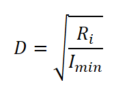
This has all kind of assumptions (the supplied maximum values can be met) and idealisations. Testing and measuring will need to provide actual data.
Note: 1 sr (steradian) is the solid angle where the area it projects to has a surface of r2, where r is the radius or distance to that surface. So at a distance of 1 m, 1 m2 is projected (or illuminated) by a solid angle of 1 sr.
Notes for testing
What we ideally want to gain knowledge about is a.o.:
- Range
- Effects of setup (opposing or using a reflector)
- Type of reflector
- Effects of sunlight
- Effects of (unwanted) reflections
- Effects of dry or wet surfaces
- Effects of rain or small droplets (e.g. fog)
- Need of optical isolation between source and detector
- Detector speed
Other posts on Timing: